2014年1月23日星期四
2014年1月22日星期三
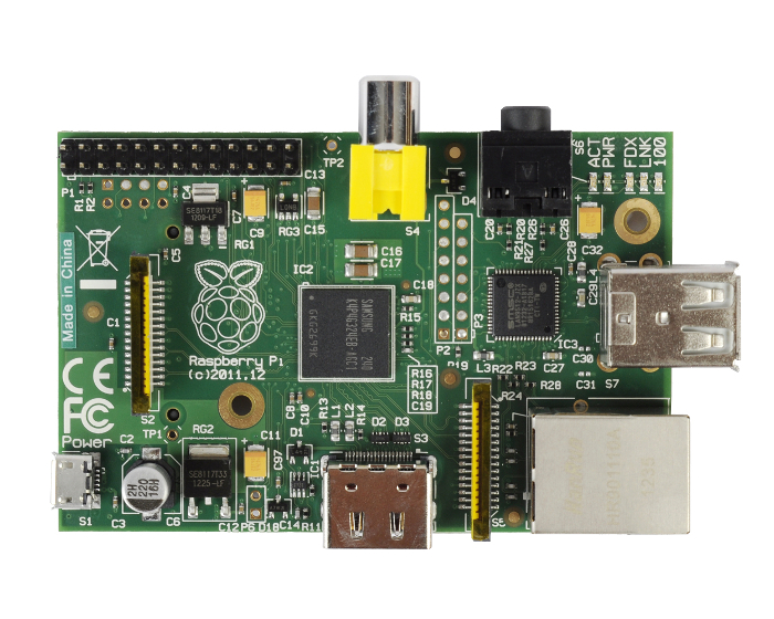
Raspberry PI is available on www.ICStation.com NOW!

2. GPU provides Open GL ES 2.0, hardware-accelerated OpenVG, and 1080p30 H.264 high-3. profile decode
4. GPU is capable of 1Gpixel/s, 1.5Gtexel/s or 24 GFLOPs of general purpose compute and features a bunch of texture filtering and DMA infrastructure
5. 512MB RAM
6. Boots from SD card, supports Linux distros such as Fedora, Debian and ArchLinux
7. 10/100 wired Ethernet
8. HDMI output
9. USB 2.0 interface x 2
10. RCA Video output
11. Standard 3.5mm jack for audio out
12. SD card slot
13. Powered by 5v micro USB
14. Camera connector
15. Dimensions: 85.60mm x 56mm x 21mm
What is Raspberry Pi?
The Raspberry Pi is a credit-card sized computer that plugs into your TV and a keyboard. It can be used for many of the things that your desktop PC does, like spreadsheets, word-processing and games. It also plays high-definition video.
Water Level Sensor Module for Arduino AVR ARM STM32 STM8
Congratulations to the ICStation team! They have developed this wonderful water level sensor module
by great efforts.This module with small size and high cost-effective is
easy to use.In this article, we will use the digital storage
oscilloscope to show you how the output voltage change with the
immersion depth.What’s more,we will show you an interesting actual
application case.You will have a clear idea of how this module to
realize the function of water level alarm.
Features: Simple ,Easy to use,Small size,Light, High Cost-Effective
Applicable Occasion:Water level alarm design
Parameter:
Working Voltage: DC5V
Working current: Less than 35mA
Type : Analog sensor
Testing area: 40mm x 18mm
Working temperature: 10℃-30℃
Working moisture: 10%-90% without condensation
Fixing hole size: Φ3mm
Product size: 60mm x 22mm


 Output Voltage: 3.22V
Output Current: 28mA


Features: Simple ,Easy to use,Small size,Light, High Cost-Effective
Applicable Occasion:Water level alarm design
Parameter:
Working Voltage: DC5V
Working current: Less than 35mA
Type : Analog sensor
Testing area: 40mm x 18mm
Working temperature: 10℃-30℃
Working moisture: 10%-90% without condensation
Fixing hole size: Φ3mm
Product size: 60mm x 22mm
Diagram
Function Introduction
Functional Test
Testing environment:barreled pure water
Testing procedures:
1.Connect the module to 5V power supply
2.Put the module to into the pure water
3.Observe the relation between the immersion depth and the output voltage of AO end.
Testing procedures:
1.Connect the module to 5V power supply
2.Put the module to into the pure water
3.Observe the relation between the immersion depth and the output voltage of AO end.
Actual testing results:
①Totally out
Output Voltage: 0V
Output Current:0mA
Output Current:0mA
②Immerse part of the module
Output Current: 28mA
③Immerse full part of the module
Output Voltage: 3.42V
Output Current: 32mA
According to the three groups of data, we can make a conclusion that the actual testing results meet the requirement of application.
Output Current: 32mA
According to the three groups of data, we can make a conclusion that the actual testing results meet the requirement of application.
Actual application case
Use this water level sensor module to control on or off about the LED which is on the arduino board.
Tools:
1.arduino uno
2.Pin Header
3.Dupont Cable
Tools:
1.arduino uno
2.Pin Header
3.Dupont Cable
2014年1月21日星期二
2014年1月20日星期一
2014年1月16日星期四
The Biggest Year Sale: 20% Off on Everything

Happy Chinese New Year!
ICStation will be on holiday from 27th, Jan to 9th, Feb to celebrate our the year of horse.
Though we could not feedback to you on time, www.ICStation.com is taking the orders as usual during this time.
And orders / emails will be processed once we're back to office on 10th, Feb.
(Orders which placed before 27th, Jan will be shipped in 2 days.)
And here we thank you for all your faithfully support of the past year!
"Making Easier Possible", we'll try our best to develop more products to meet your requirements and continue to provide all you with high quality & reasonable price products and best services.
At last but not least, ICStation team wish all you have a prosperous and happy new year. :)
Best regards,
ICStation Team
2014年1月12日星期日
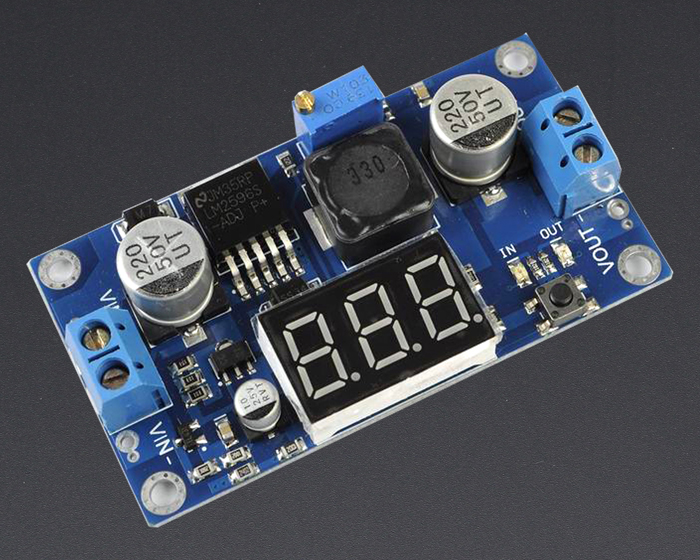
The Introduction of LM2596 Step Down Power Module DC-DC Converter
1.With voltage meter display;voltage meter error of ±0.1V;the range among 0~40V. (note: to ensure the voltage meter accuracy, please make sure that the input voltage is 4.2V or more).
2.Voltage meter can be closed by long pressing button(minimum power loss).
3.The range of input voltage is 4.2~40V and output voltage is1.25V~37V ,which are continuously adjustable.(The input voltage must 1V higher than output voltage)
4.Maximum output current can be as high as 3A,but normal and stable working current is2A.
5.Use 150KHZ internal oscillation frequency,which is belong to the second generation of switch voltage regulator with low consumption and high efficiency.
Where to use:
1.experiment teaching
2.temporarily set up power supply in the outdoor
3.car(audio, electric fan)power supply
What is special:
LM2596 Step Down Power Module design based on XL2596 as main control chip,attached digital tube to display voltage at that time to highlight smart function. What’more, schottky diode provides protection of reverse connection.
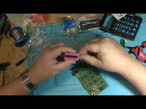
What components and tools do you need to do the test: Copper Wire Copper Cylinder Nut Pin Header Screw Driver Power Connector
Function Introduction

Diagram

Testing Results:Input voltage 4.5V

Testing Results:Input voltage 30V

In general, the performance of LM2596 Step Down Power Module is very good.You had better set the output voltage 3~4V lower than the input voltage, then the testing results will be more stable.
2014年1月10日星期五
2014年1月9日星期四
The Introduction of LM2596 Step Down Power Module DC-DC Converter

ICStation Team share this LM2596 Step Down Power Module with you in details. We will introduce the features,scope of application,diagram,and testing results.We
use the digital storage oscilloscope to test the module and show you
the actual testing results with pictures.You will have a full
understanding of this module.
Features
1.With voltage meter display;voltage meter error of ±0.1V;the range among 0~40V. (note: to ensure the voltage meter accuracy, please make sure that the input voltage is 4.2V or more).
2.Voltage meter can be closed by long pressing button(minimum power loss).
3.The range of input voltage is 4.2~40V and output voltage is1.25V~37V ,which are continuously adjustable.(The input voltage must 1V higher than output voltage)
4.Maximum output current can be as high as 3A,but normal and stable working current is2A.
5.Use 150KHZ internal oscillation frequency,which is belong to the second generation of switch voltage regulator with low consumption and high efficiency.
Where to use:
1.experiment teaching
2.temporarily set up power supply in the outdoor
3.car(audio, electric fan)power supply
What is special:
LM2596 Step Down Power Module design based on XL2596 as main control chip,attached digital tube to display voltage at that time to highlight smart function. What’more, schottky diode provides protection of reverse connection.
What components and tools do you need to do the test:
Function Introduction
Diagram
Testing Results:Input voltage 4.5V
Because the starting voltage is 4.2V, when testing you should set the input voltage 4.5V and the output voltage 1.4V. ICStation
Team test it on the digital oscilloscope and the result shows that the
actual testing of the product is in accordance with the description.
Testing Results:Input voltage 30V
In general, the performance of LM2596 Step Down Power Module is very good.You had better set the output voltage 3~4V lower than the input voltage, then the testing results will be more stable.
Thank you for your visiting! Please feel free to share us your comments. :)
Should you meet any problem, please feel free to contact us.
ICStation Team
Weekly Surprise Sale
$1.59 + Free Shipping
Hurry Up to Get, 7 Days left

- Breadboard power supply module, compatible with 5 V, 3.3 V
- Apply to MB102 breadboard
- Input voltage: 6.5-12 V (DC) or USB power supply
- Output voltage: 3.3V/5V can switch over
- Maximum output current: <700 ma
- Fluctuation two road independent control, can switch over to 0V, 3.3V, 5V
- On-board two groups of 3.3V, 5V DC output plug pin, convenient external lead use
2014年1月8日星期三
2014年1月7日星期二
2014年1月6日星期一
2014年1月5日星期日
ICStation First Smart Car: Android Smart Phone Bluetooth Remote Control Intelligent Smart Car 51 MCU

At the beginning of the new year, robot/Smart Car hobbyists and students (like all of you) about engineering, science and technology are busy with preparing for the robot competitions now.
It’s the great time to show the world your imagination and potential now.
ICStation R&D department has just finished this obstacle avoidance intelligent smart car which based on the STC89C52 MCU. It features with the function of obstacle avoidance, infrared remote control and Bluetooth remote control system. It improves a lot on the usage of this intelligent smart car via the connects of various modules and controller.
BTW, this is just a sample which based on 51 MCU for your reference. You also can use other MCU to build your own gear. If you like 51, just leave us your email address to get the testing code.
Outline
- Main Parts Parameters
- Components
- Steps for installation Intelligent Smart Car
- Main Components Introduction
Parameters for your reference: 1. Motor parameter
- Power apply:6V-9V
- Reduction gear ratio:1:48
2. Dual L298 Driver Motor Module
- Driver chip: L298N dual H-bridge driver chip
- Drive section terminal supply area VMS: +5V ~ +16V. (The supply area should be +6V~+16V if the electricity should be taken in the plate.)
- Drive section peak current Io: 2A / Bridge
- Logical part of the terminal supply area Vss :+5V~+7V (the electricity can be taken in the plate +5V.)
- Logical part of the operating current range: 0 ~ 36mA
- Control signal input voltage range (IN1 IN2 IN3 IN4):
Low Level:-0.3V≤Vin≤1.5V
High level: 2.3V≤Vin≤Vss
- ENA ENB
Low Level:-0.3≤Vin≤1.5V (Control Invalid Signal)
High level: 2.3V≤Vin≤Vss (Control Valid Signal)
3. Ultrasonic module
Working Voltage : 2.4~5.5v
Static current: Less than 2mA
Detection distance range: 0~4.5m
Components
1 x 4WD Smart Car Chassis $31.54
4 x Motor Reduction
1 x 7.2V Battery pack
1 x Speed Sensor $5.6
1 x L298N 4 Channels Step Motor Driver Module
40 x Dupont 20cm Color Cable
1 x SG90 Micro Servo Motor $3.04
1 x Bluetooth Transeiver RF Module
1 x US-100 Ultrasonic Sensor Module $5.46
1 x 4 Channel Tracing Module
1 x 51 MCU
4 x Infrared Sensor Obstacle Avoidance Module Probe
1 x Ultrasonic bracket
1 x Infrared Remote Control Module $2.8
1 x Steering Gear Bracket
6 x Copper Cylinder M3*45+6
1 x M3*7.5 screw
Step 1: Installation of smart car wheels
- Fix the motor and the base plate with 2pcs fixed plates and 2pcs
screws (The side with the line ends of the motor should be faced
inward.)
- Install the encoder and wheel
(no need to do this if you have the 4WD kits on hand)

Step 2: Install the Speed measuring module on the baseboard

Step 3: Install the 4pcs of obstacle avoidance probes on the baseboard

Step 4: Fix six pillar with 3.5cm on either side of the baseboard

Step 5: Fix the 51MCU module, 4 channel tracing module, Dual L298 drive module on the top plate

You also can use other MCU to build your own gear. If you like 51, just leave us your email address to get the testing code.
Step 6: Install the SG90 on the top plate and fix the top plate and baseboard

Step 7: Install the US-100 Ultrasonic Sensor Module on the SG90

Step 8: Wire Connection

Download the wire connection table which based on the STC89C52 MCU here: http://www.icstation.com/newsletter/eMarketing/STC89C52_wire.pdf
Please feel free to contact us if you have any unclear or need any parts or material from us.
Thanks!
Best regards,
ICStation Team
订阅:
博文 (Atom)
-
Dear friends, Hope everything goes well with you! Today we are going to introduce 1 of our latest hot sale new products, hope you will like...
-
Introduction Standard double panel design,fine workmanship, board size:38mm X 30mm Use ULN2003 drive chip,50...
-
Hi, dear friend! Thanks for your support of ICStation for all the time! We now have 5-10 New Products per week. We're trying ...


Electronics Calculator Kit Build
1.Introduction: ICStation Multi-functional Calculator DIY Kit is powered by two CR2032 button batteries, integrates five different comput...