Translate

2021年3月26日星期五

ICStation Weekly New Products: MAX30102 Pulse Oximeter Heart Rate Sensor +5.8G Microwave Radar Sensor

Dear friends,

Hope everything goes well with you! 

Today we are going to introduce 3 of our weekly new products, which was ordered by customers in a short time after sold on the website, hope you will find any of the one that you may like.

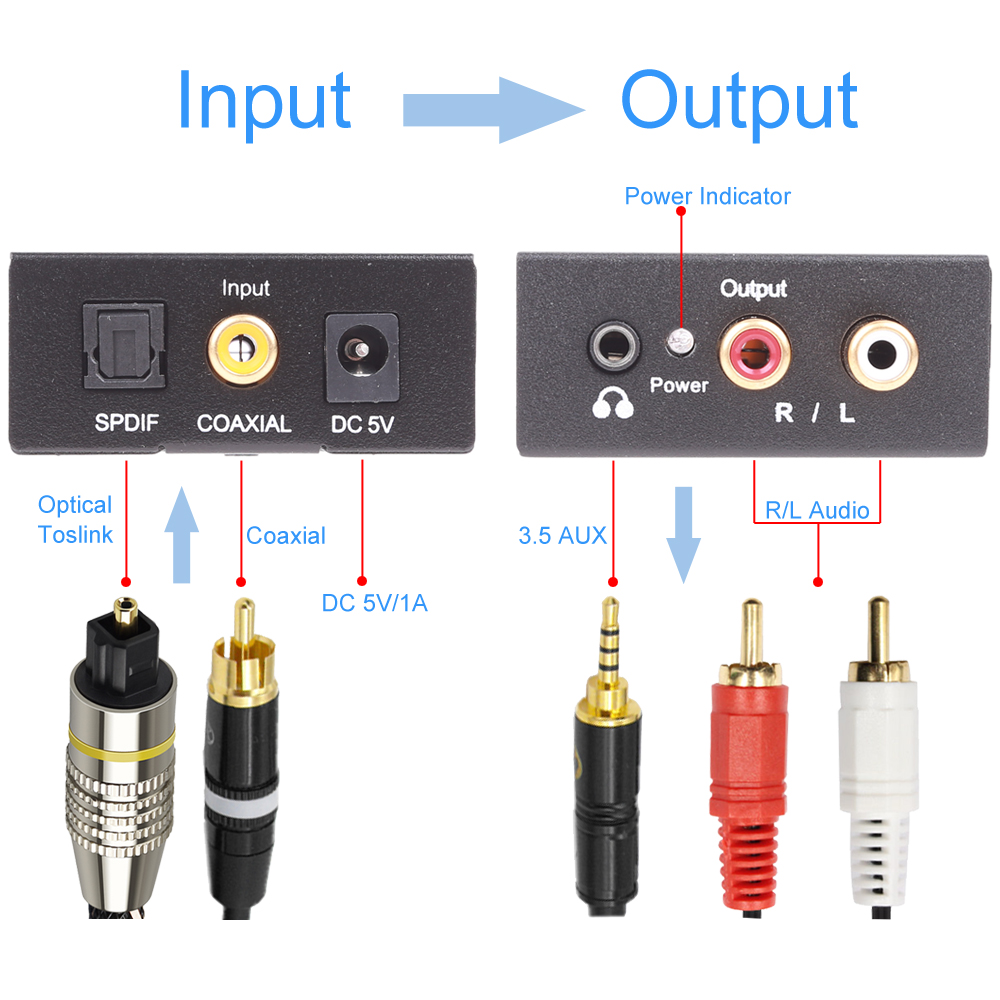
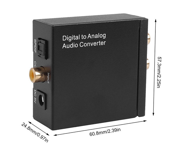
No. 1: DAC Digital to Analog Audio Converter Coaxial Toslink to Analog Stereo L/R RCA 3.5mm Jack Audio Adapter with Optical Cable
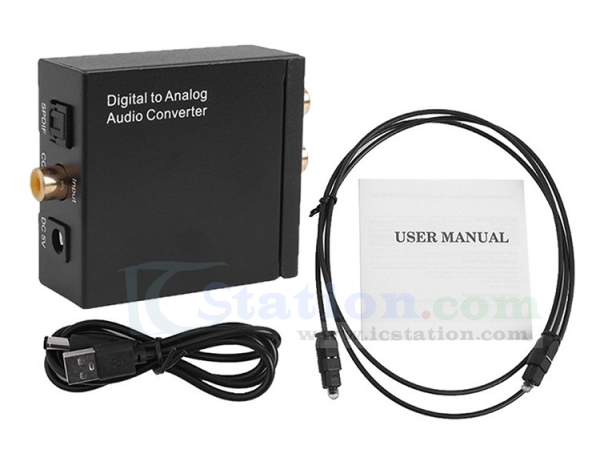


The device successfully decodes perfectly and sends the audio signal without damage and noise into the audio amplifier! Achieve perfect high fidelity lossless audio output function! Perfect audio visual!

Updated Digital to Analog Audio Converter】: It converts coaxial or toslink digital PCM/LPCM audio signals to analog L/R RCA and 3.5mm Jack Audio (not capable of being reversed). This Digital to Analog Audio Converter is designed for either home or professional audio switching.

It can be used in digital LED TV / cloud TV / Apple TV / blue ray machine / network player / XBOX360 / computer optical fiber coaxial output sound card / digital set top box / network TV box and other electrical equipment with SPDIF coaxial audio / digital optical fiber audio output equipment which can use this converter to convert to analog audio signal L/R channel output.

96KHz Sampling Rate】: Supports sampling rate at 32, 44.1, 48 and 96KHz; 24-bit S/PDIF incoming bit stream on left and right channels. Provides electromagnetic noise-free transmission.  

Easy operation & Wide Application】: With an optical cable and a coaxial cable to transmit digital or analog signals respectively, powered by (5V 1A) USB power cable(Does not come with adapter). Easy to install and simple to operate. 


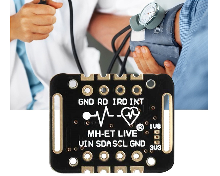
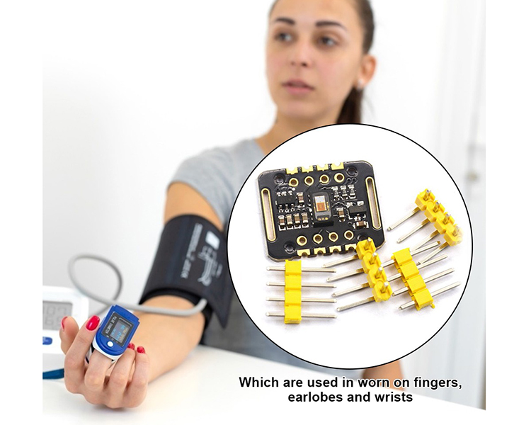
No. 2: MAX30102 1.8V-5V Pulse Oximeter Heart Rate Detection Sensor


MAX30102 blood oxygen concentration sensor. An integrated pulse oximeter and heart rate monitor biosensor module.

It uses an 18V power supply and an independent 50V power supply for internal LEDs, which are used in wearable devices for heart rate and blood oxygen collection and detection.
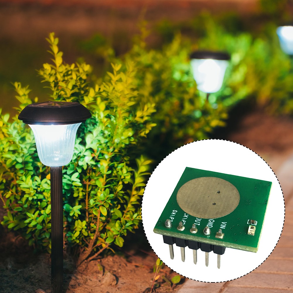
No. 3: 5.8G Microwave Radar Module Infrared Human Body Detector
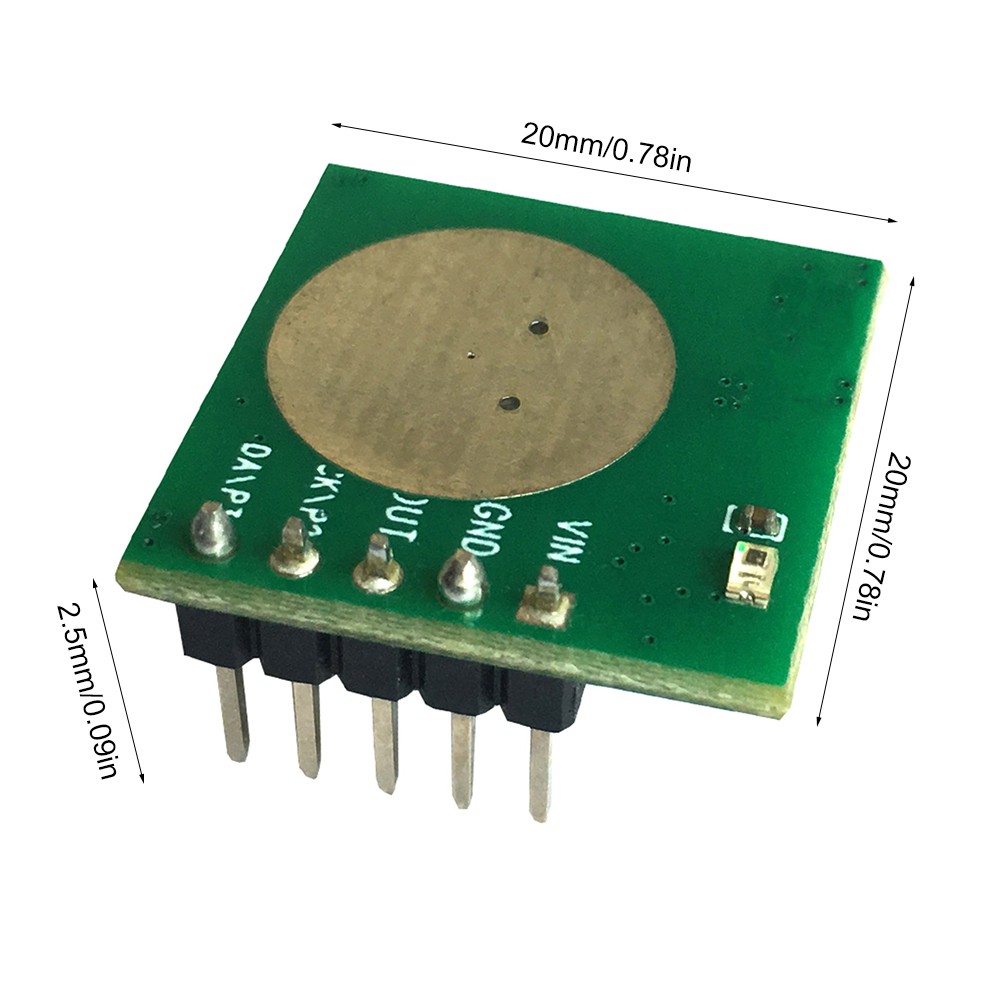

This is an ultra-low power 5.8G microwave radar module with a working current of only 68uA. 

Combines the high performance of microwave induction and the ultra-high cost-effectiveness of infrared induction. 

Its sensing distance and delay time can be adjusted.
It can perfectly replace infrared pyroelectric induction and make up for the lack of infrared induction. 

Thank you for your attention! For more new products, please check ICStation.com:)

2021年3月10日星期三

Latest Hot Sale New Products!!! FM Radio Wireless Receiver Kits and DC-DC Power Module Recommended!

Dearest Friends,

Much thanks for your support all the way! ICStation has run business for 8 more years now! 2020 is a hard year due to the unexpected COVID-19, many companies closed down, but because of your continues support, we still alive. We still able to provide new products, ship to most of the countries as usual now.

Recently we have some Hot sale new products, especially the FM Radio Kits were very popular and loved by customers. Now Let's look at our latest top 3 new arrivals ! They are might be a nice choice for your new electronics project at the beginning of March! 


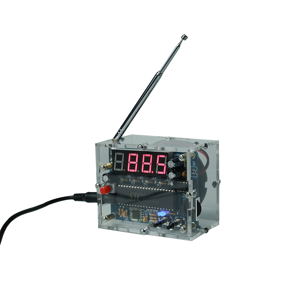
It is an 87.0MHz-108.0MHz Wireless FM Radio Receiver DIY Kit. 
With a built-in 4-Bit Red Digital Tube display screen which can display the receiving frequency clearly.


General Features:
1.Automatically search for radio stations
2.Built-in volume adjustment
3.Automatic memory function after power off
4.Support 87Hz-108MHz receiver frequency
5.Built-in 5W power amplifier
6.Power saving mode with backlight off for 5 seconds

Parameter:
1.Product Name:FM Radio Receiver DIY Kit
2.Work Voltage:DC 4.5V~5.5V
3.Output impedance:8ohm
4.Output power:5W
5.Output channel:Mono
6.Receiver Frequency:87.0MHz~108.0MHz
7.Frequency accuracy:0.1MHz
8.Equivalent noise: >=30dB
9.Work Temperature:-40℃~85℃
10.Work Humidity:5%~95%RH
11.Size(Installed):83*69*53mm

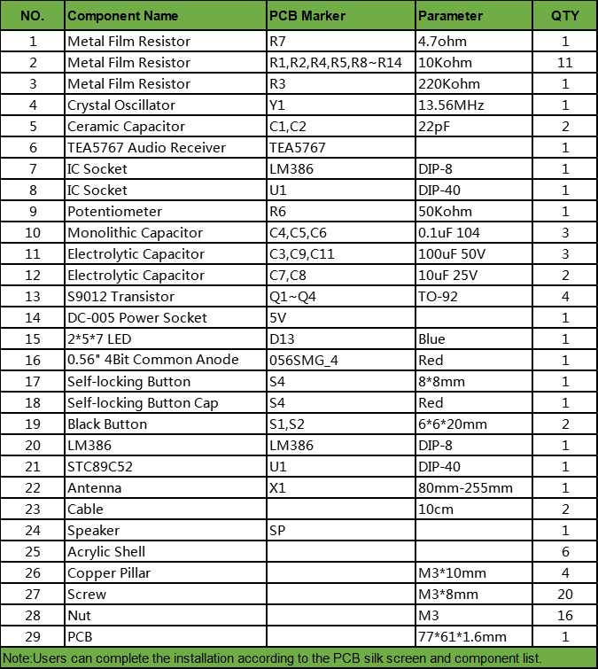
Component List:


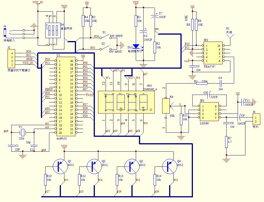
Schematic Diagram:


Notice:
1.The frequency can be adjusted continuously by keep press button.
2. It is a wireless module. So do not use it in an environment with signal interference.
3.The display can only show for 5 seconds and then enter to power saving mode.

Using Methods:
1.Press left button to decrease receiving frequency.
2.Press right button to decrease receiving frequency.
3.Rotate potentiometer to adjust the volume.

Installation Steps (Please be patient):
Step 1: Install 1pcs 4.7ohm Metal Film Resistor at R7.
Step 2: Install 1pcs 220Kohm Metal Film Resistor at R3.
Step 3: Install 11pcs 10Kohm Metal Film Resistor at R1,R2,R4,R5,R8~R14.
Step 4: Install 1pcs TEA5767 Audio Receiver at TEA5767.Pay attention to the installation direction.
Step 5: Install 1pcs 13.56MHz Crystal Oscillator at Y1.
Step 6: Install 2pcs 22pF Ceramic Capacitor at C1,C2.
Step 7: Install 1pcs DIP-8 IC Socket at LM386.There is a mark on one end of the IC Socket and there is a mark on PCB where the IC Socket can place on.These two marks are corresponding to each other and are used to specify the installation direction of the IC Socket.
Step 8: Install 1pcs DIP-40 IC Socket at U1.There is a mark on one end of the IC Socket and there is a mark on PCB where the IC Socket can place on.These two marks are corresponding to each other and are used to specify the installation direction of the IC Socket.
Step 9: Install 1pcs 50Kohm Potentiometer at R6.
Step 10: Install 3pcs 0.1uF Monolithic Capacitor at C4,C5,C6.
Step 11: Install 4pcs TO-92 S9012 Transistor at Q1~Q4.
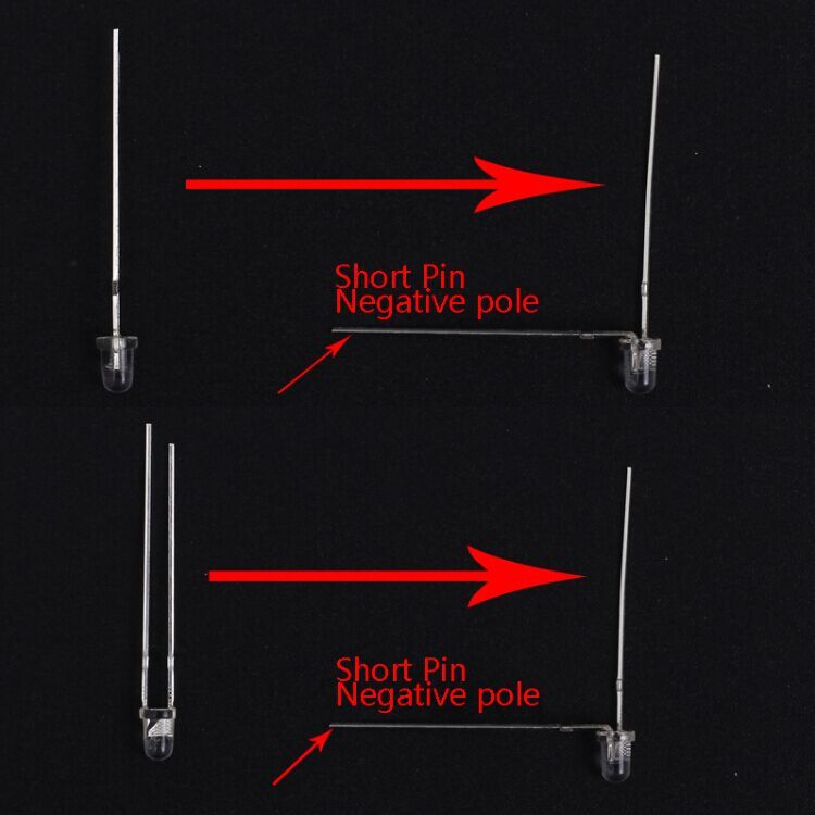
Step 12: Install 2pcs 10uF 25V Electrolytic Capacitor at C7,C8.Pay attention to distinguish between positive and negative.The Longer pin is positive pole.
Step 13: Install 1pcs Blue 2*5*7 LED at D13.Pay attention to distinguish between positive and negative.The Longer pin is positive pole.
Step 14: Install 1pcs Red 0.56" 4Bit Common Anode Digital Screen at 056SMG_4.Pay attention to the installation direction.
Step 15: Install 1pcs DC-005 Power Socket at 5V.
Step 16: Install 3pcs 100uF 50V Electrolytic Capacitor at C3,C9,C11. Pay attention to distinguish between positive and negative.The Longer pin is positive pole.
Step 17: Install 1pcs Self-locking Button at S4.
Step 18: Install 2pcs 6*6*20mm Black Button at S1,S2.
Step 19: Install 1pcs DIP-8 IC LM386.There is a mark on one end of the IC and there is a mark on PCB where the IC can place on.These two marks are corresponding to each other and are used to specify the installation direction of the IC.
Step 20: Install 1pcs DIP-40 IC STC89C52.There is a mark on one end of the IC and there is a mark on PCB where the IC can place on.These two marks are corresponding to each other and are used to specify the installation direction of the IC.
Step 21: Install 1pcs Antenna at ANT.Note that the antenna should be installed on the back of the PCB.
Step 22: Connect speaker to PCB at SP by 10cm red/black Cable. The speaker does not distinguish between positive and negative.
Step 23: Tear off the protective film on the surface of the acrylic shell.
Step 24: Fixed speaker on acrylic bottom plate by 4pcs M3*8mm Screw and 4pcs M3 Nut.
Step 25: Install 4pcs M3*8mm Screw and 4pcs M3 Nut on PCB.
Step 26: Install 4pcs M3*10mm Copper Pillar on PCB.
Step 27: Install 4pcs M3*8mm Screw and 4pcs M3 Nut on acrylic front plate.
Step 28: Install PCB module on acrylic front plate.
Step 29: Fix other acrylic plate by 12pcs M3*8mm Screw and 12pcs M3 Nut.
Step 30: Connect to power supply and enjoy the effect.


DIY Kit FM Radio Module Adjustable 76-108MHz Wireless Receiver LCD Display DC 3.7V 5W 8ohm Speaker


Feature:
1.HD display LCD display screen
2.Support storage of 22 radio stations
3.Automatically search for radio stations
4.Built-in 30-level digital volume adjustment
5.Automatic memory function after power off
6.Support 76Hz-108MHz receiver frequency
7.Built-in rechargeable module
8.Built-in 5W power amplifier
9.Power saving mode with backlight off for 20 seconds
10.Support speaker and earphone audio output

Parameter:
1. Work Voltage:DC 3.0V~5.0V
2.Output impedance:8ohm
3.Output power:5W
4.Output channel:Mono for speaker and Dual channel for earphone
5.Frequency:87.0MHz~108.0MHz(Disable Campus Broadcasting Band)
6.Frequency:76.0MHz~108.0MHz(Enable Campus Broadcasting Band)
7.Equivalent noise: >=30dB
8.Work Temperature:-40℃~85℃
9.Work Humidity:5%~95%RH
10.Size(Installed):118*87*27mm

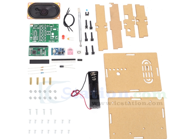
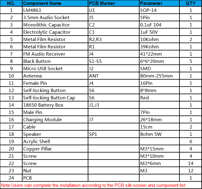
Component List:


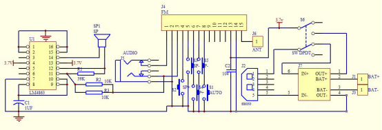
Schematic Diagram:


Notice:
1.It cannot receive radio while it is charging.
2.It is a wireless module. So do not use it in an environment with signal interference.
3.Input charging voltage form micro USB on the bigger PCB.

Installation Steps:
Step 1: Install 1pcs 39Kohm Metal Film Resistor at R1.
Step 2: Install 2pcs 10Kohm Metal Film Resistor at R2,R3.
Step 3: Install 1pcs SOP-14 IC LM4863 at U1.There is a mark on one end of the IC and there is a mark on PCB where the IC can place on.These two marks are corresponding to each other and are used to specify the installation direction of the IC Socket.
Step 4: Install 1pcs micro USB socket at J2.
Step 5: Prepare 6pcs pin header.
Step 6: Install 1pcs Charging Module at J7 and fix by 6pcs pin header.
Step 7: Remove black fixed block from 6pcs pin header and fix Charging Module.
Step 8: Install 1pcs 0.1uF Monolithic Capacitor at C2.
Step 9: Install 1pcs 1uF 50V Electrolytic Capacitor at C1.Pay attention to distinguish between positive and negative.The Longer pin is positive pole.
Step 10: Install 1pcs 3.5mm Audio Socket at J5.
Step 11: Cut a pin from 16Pin Female Socket.
Step 12: Install Female Socket at FM.Pay attention to the direction of the cut pin.
Step 13: Install 1pcs Self-locking Button at S6.
Step 14: Install 5pcs 6*6*20mm Black Button at S1-S5.
Step 15: Install 1pcs Self-locking Button Cap on Self-locking Button.
Step 16: Install 1pcs Antenna at ANT.Note that the antenna should be installed on the front of the PCB.
Step 17: Install 1pcs 18650 Battery Box at J1,J3.Pay attention to the positive and negative.Red wire is positive pole.
Step 18: Install 2pcs 15cm black Cable on speaker.
Step 19: Connect speaker to PCB at SP. The speaker does not distinguish between positive and negative.
Step 20: Install 1pcs FM Audio Receiver on Female pins.Pay attention to the direction of the cut pin.
Step 21: Tear off the protective film on the surface of the acrylic shell.
Step 22: Install 4pcs M3*15mm Copper Pillar and 4pcs M3*10mm Screw on Acrylic bottom plate.
Step 23: Fixed speaker on acrylic bottom plate by 4pcs M3*6mm Screw.
Step 24: Install 3pcs M3*6mm Screw and 3pcs M3 Nut on Acrylic bottom plate.Note that the wire should not be placed between the PCB and the acrylic.
Step 25: Fixed main PCB on acrylic bottom plate by 3pcs M3 Nut.Note that the wire should not be placed between the PCB and the acrylic.
Step 26: Adjust the position of the battery box. Do not place the wires under the battery box. The wires can be moved to both ends of the battery box.
Step 27: Fix other acrylic plate by 6pcs M3*6mm Screw and 6pcs M3 Nut.
Step 28: Connect to power supply and enjoy the effect.

Use Method:
1.Keep press AUTO button to automatically search and store the radio stations that can be listened to.
2.Automatically name searchable stations like P01,P02,P02 and so on.
3.Press P+ and P- to switch saved stations.
4.Press V+ and V- to adjust volume from V00 to V30.
5.Switch Campus Broadcasting Band: Keep press V+ and V- before power ON and then turn ON work power switch. It means enable Campus Broadcasting Band if display C1 on LCD. It means disable Campus Broadcasting Band if display C0 on LCD.Available after restart.
6.Enable backlight mode: Keep press P+ and P- before power ON and then turn ON work power switch. It means keep backlight ON if display B1 on LCD. It means the backlight will turn OFF after 20second if display B0 on LCD(This is the power saving mode). Available after restart.
7.It can output audio from speaker and earphone jack. The speaker of the module does not work when the earphone is connected.


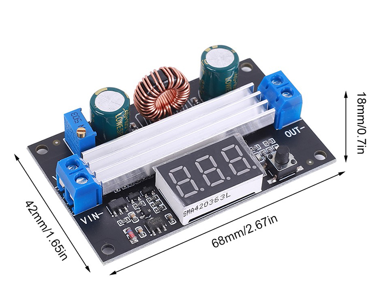
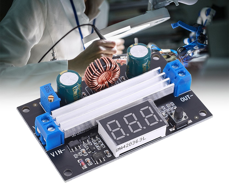
DC-DC Boost Power Supply Module DC 3V-35V to DC 3.5V-50V 6A 100W High Power Digital Display

Product Introduction:
It is a booster board, the output voltage is greater than the input voltage. When the output voltage is less than 4V, the onboard voltmeter will not work.

Feature:
1.It has a digital display to display voltage.
2.Its conversion efficiency is high.
3.It has an output voltage potentiometer to adjust the voltage in time.
4.It has a display switch button to switch between input voltage display and output voltage display.

Parameter:
1.Product Name:Boost Module
2.Input Voltage:DC 3.3~35V
3.Input Current:9A(Max)
4.Output Voltage:DC 3.5~50V
5.Output Current:6A(Max)
6.Output Power:100W (input voltage greater than 12V can reach the maximum output of 100W)
7.Conversion Efficiency:96%(Max)
8.Output Ripple:40mV(TYP)
9.Range of Onboard Voltmeter:3~55V
10.Work Temperature:-25℃~85℃
11.Work Humidity:5%~95%RH
12.Size:68*42*18mm

Instructions for Use:
1.The voltmeter can be turned off.Press and hold the switch for 4 seconds,and then it can be turned off by letting go.

2.Input and output voltage measurement error calibration function,long press the switch for more than 4 seconds,after letting go,it will enter the voltage measurement error calibration function.

3.The digital tube flashes to display the voltage calibration ratio value (range -5V~5V).At this time,short press the button to change this value (cycle between -5V~5V).

4.When the voltage value displayed by the voltmeter is too high,lower the reference value (adjust to a negative number).

5.When the voltage value displayed by the voltmeter is low,increase the reference value (adjust to a positive number).

6.After adjusting to the reference value you want,press and hold the button for more than 2 seconds. After letting go,save the set value and return to the normal display voltage.The set correction value will take effect immediately and will not be lost after power failure.


Thanks for your time! We will have more new arrivals soon! 

2020年12月20日星期日

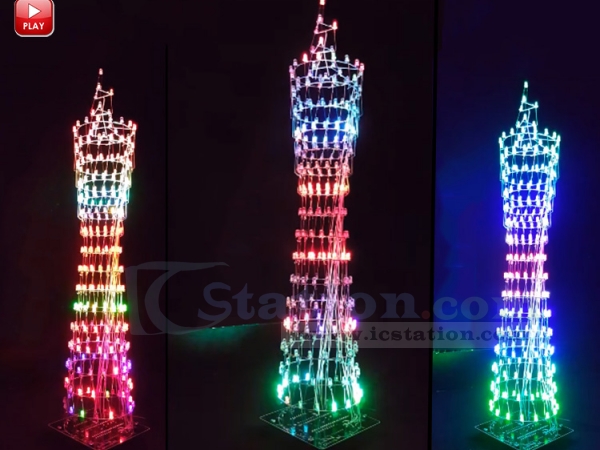
ICStation colorful LED tower display rhythm light kit


Introduction:

1. LED Tower is imitated from Guangzhou Tower. Guangzhou Tower, also known as Guangzhou new TV tower, nickname Xiaoman Yao.

2. It is the tallest building in Guangzhou, the design of the tower is very characteristic, especially in the night under the lighting decoration, very beautiful.

3. Now it becomes a landmark in Guangzhou (a city of China). We combined with the single-chip micro-chip display technology to make the beauty of the Guangzhou Tower.

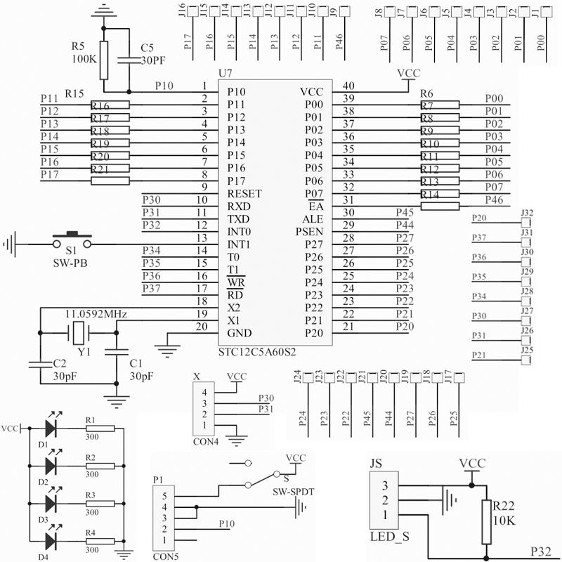
4. Using STC12C5A60S2 as a control system, the display part is 16*16 dot matrix display, through the production of the Guangzhou Tower, can better enhance the microcontroller on the principle of dot matrix display.


Application:
1.Home Furnishing decoration
2.Store decoration
3.Graduation design
4.Practice for electronic enthusiasts
5.Holiday gifts

http://www.icstation.com/colorful-tower-display-rhythm-lamp-light-with-infrared-remote-control-electronic-kits-brain-training-gifts-p-12320.html

2020年1月11日星期六

New ESP Wireless WIFI Transceiver Modules Recommended

Dearest Friends,

Thank you very much for reading this article.

Recently we have some New Products about ESP module. Some of them are really popular with good price. Hereby, we would like to recommend some of them to you, which might be a good choice for you to start new project in the beginning of 2020.

No.1# ESP8266 0.96 Inch OLED Weather Clock Display RTC ESP-12F Wireless WIFI Transceiver Module


1.Description:
  It is a RTC Weather ESP8266 0.96inch OLED Display Module. It can display current time and weather on OLED display screen.
 
2.Feature:
  1>.Built-in ESP-12F WIFI Module
  2>.Built-in 4M BYTE FLASH
  3>.IIC 0.96in OLED Display Screen
  4>.Built-in Clock chip
  5>.Reserved UART interface
 
3.Parameter:
  1>.Work Voltage:DC 5V
  2>.OLED Driver IC:SSD1306

Discount Price: $6.99.
Click here to know more info about this item: ESP8266 0.96 Inch OLED Display Module 


No.2# Infrared Transceiver ESP8285 Wireless Transceiver Module WIFI Remote Control Switch


1.Description:
  It is a Infrared ESP8285 Wireless WIFI Transceiver Module. The esp-01m module with ESP8285 as the core be used as the master control, the program is the same as ESP8266. The module is equipped with an infrared receiving tube and an infrared transmitting tube which are respectively io14 and io4 controlled, and a burning port sets apart.
 

  The demonstration program can read and emit infrared key values and raw codes, user can record infrared remote controls in your home , which can be controlled remotely if connected to the Internet of things platform.

2.Feature:
  1>.Support Infrared control
  2>.Support wireless WIFI control
  3>.Support firmware update

  If you are interested in it, click here for more info and get it at $4.19 : Infrared ESP8285 Wireless WIFI Transceiver

No.3# ESP8266 WIFI Wirelesss Transceiver Module Support Airkiss Protocol UART TTL Control


1.Description:
  It is a ESP8266 WIFI Wirelesss Transceiver Module. It based on ESP8266EX controller, supports data transparent transmission function and Airkiss protocol.
 
2.Feature:
  1>.UART to WIFI data transparent transmission
  2>.Support STA,AP and WIFI mode
  3>.Low power consumption

Click here and get it at $4.19: ESP8266 WIFI Wirelesss Transceiver

Not the one you are looking for? It doesn't matter!
ICStation will have 5-10 New products per week.  And each week we will have promotion activies to thanks for all of your support and attention. Please continue to support us in the future:)

By the way, we'll be 10 days off for the holiday from Jan 23rd-Feb 1st. All your emails and orders will be disposed when we back to work on Feb 2nd. Thanks for your support and enjoy your shopping as usual ^0^

2019年11月19日星期二

PWM to Voltage Adjustable Converter Module 0%-100% to 0-10V _ICStation.com


PWM to Voltage Converter Module 0%-100% to 0-10V PWM Adjustable Converter Power Module for PLC MCU Digital to Analog Signal


Description:
1. The PWM transfer voltage module LC-LM358-PWM2V converts the PWM digital signals into 0 to 10V analog signals.
2. It can be used as signal interface switching for PLC or other industrial control boards. The output voltage is regulated by adjusting the duty ratio of the PWM.
   The modules are small in size and easy to use in different places.

Features:
1>. MCU embedded technology
2>. Easy to operate, fine tuned by potentiometer
3>. Select the PWM signal input level range through short-circuit
4>. The module is smaller, easy to carry and use

Parameter:
1>. Work Voltage:DC 12V-30V; (> 100MA)
2>. PWM Receiver Frequency:1KHZ-3KHZ
3>. PWM signal input level range:
    The peak of 4.5V to 10V level. The short cap install in ‘5V’. This level is used for normal controller or 5V MCU
    The peak of 12V to 24V level, so inserted in 24V. The short cap install in ‘24V’. This level is used for normal PLC controller
4>. Conversion range:0%-100% PWM to 0-10V
5>. Allowable error:5%

Hardware Interface:
VCCDC 12V-30V
GNDGround
PWMPositive of PWM input signal
GNDNegative of input signal
VOUTOutput Voltage 0-10V
GNDOutput Voltage Ground

Operation instructions:
After power on, without input signal, the output is 0V, so only input can output.
The first time when the power is on, it is best to do a calibration debugging: Input a 50% duty ratio signal to PWM/GND and adjust the relative amplitude short cap.
The frequency is 1KHZ-3KHZ, Measured VOUT and GND with a multimeter and it will display 5V.
Adjust potentiometer to make sure display 5.00V on multimeter. This will calibrate your pulse signal to this module.
When the frequency changes, the correspondences may be offset and need to be re calibrated.
The output voltage can be adjusted by adjusting the duty ratio.
The accuracy can be controlled by adjusting the potentiometer.

You can find more Voltage converters from ICStation official website.

\


2019年10月31日星期四

4-Channel PLC Amplifier Optical Optocoupler Isolator NPN Output_ICStation.com

Hi, dear friend!

Thanks for your support of ICStation for all the time!
We now have 5-10 New Products per week. 
We're trying to provide more Fun and Useful items for your projects, with Better service and application.

Optocouplers are one of the Best sellers here, many company bought it in bulk. They are really one ingenious electronic invention....master it and you can create circuits with amazing functionality & designs.

Today, we'd like to introuduce a New Optocoupler for you:

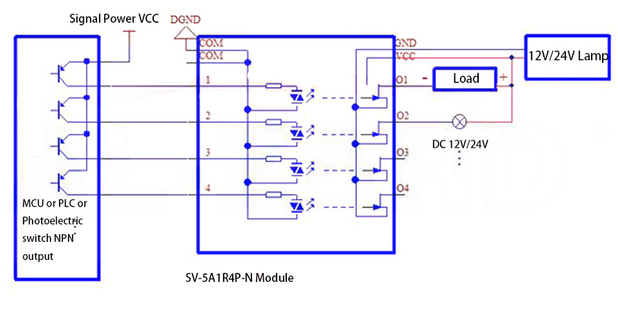
DC 3.3V 4-Channel PLC #Amplifier Optical #Optocoupler #Isolator NPN Output Signal Converter Board

13672

1.Description:
1>. Adopt new original imported FET.
2>. The input signal is compatible with NPN and PNP, and is compatible with PLC equipment such as Mitsubishi, Panasonic, Siemens, and domestic PLC.
3>. The signal input voltage is 3.3V.
4>. Protection measures: Each channel of the input adopts photoelectric isolation module to effectively protect the safety of the control terminal; at the same time, it is equipped with eight bipolar status indicators. The output has diode anti-surge protection, and the power supply has diode anti-reverse protection.
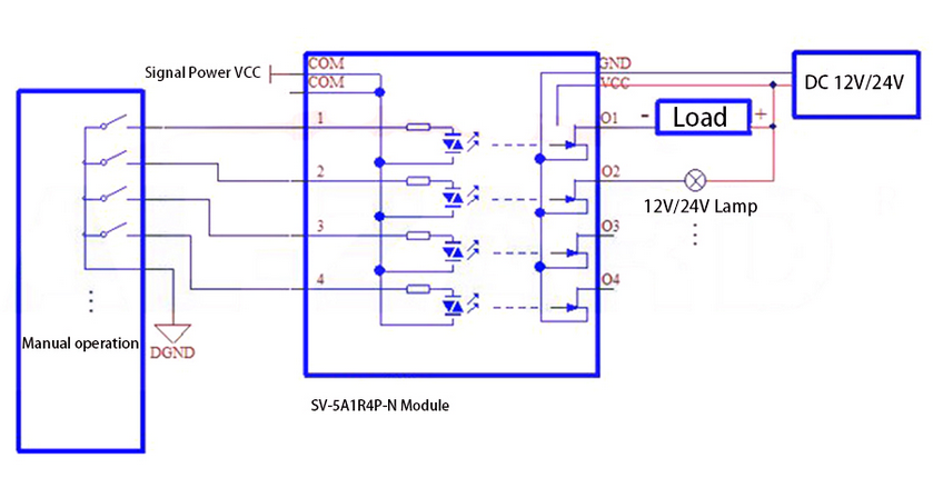
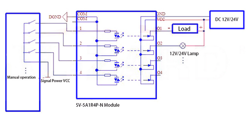
5>. Wiring: VCC and GND are the power supply ports of this module, and are wired according to the prompt voltage. COM is connected to the signal control terminal common pole, 1-4 is connected to each channel control signal; the output of the controlled device is open drain output, labeled O1-O4.
6>. Installation: DIN35mm rail installation, convenient and fast!

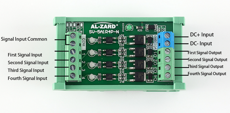
2.Pin terminal definition
  1>.COM--signal input common port
  2>.1--first signal input
  3>.2--second singnal input
  4>.3--third singnal input
  5>.4--fourth signal input
  6>.+24V--DC+ input
  7>.GND--DC- input
  8>.O1-first signal output
  9>.O2-second signal output
  10>.O3-third signal output
  11>.O4-fourth signal output


Tested by ICStation outstanding partner


2018年5月31日星期四

Hot Sale!!! STM32F4 Micropython Board from ICStation.com

Dearest Friends,

Much thanks for your order and join our website. Here we have this Hot Micropython Board recommendation to you. 

Click here to get: http://www.icstation.com/stm32f4-micropython-board-stm32f405rgt6-pyboard-stm32-micropython-core-development-board-module-flash-1924kb-sram-with-wire-p-11882.html

The #MicroPython #CoreBoard brings everything necessary for getting started in μPython with the #STM32. In addition, thanks +BitBastelei wonderful project about it. ^0^

Product Description:
  • MicroPython is a lean and efficient implementation of the Python 3 programming language that includes a small subset of the Python standard library. And it is optimized to operate on microcontrollers and in constrained environments.

  • The MicroPython pyboard is a compact electronic circuit board which operates MicroPython on the bare metal. It provides you a low-level Python operating system which can be used to control all kinds of electronic projects.

  • MicroPython is packed full of advanced features such as an interactive prompt, arbitrary precision integers, closures, list comprehension, generators, exception handling and more. Also it's compact enough to fit and operate within just 256k of code space and 16k of RAM.

  • MicroPython aims to be as compatible with normal Python as possible to allow you to transfer code with ease from the desktop to a microcontroller or embedded system.

  • MicroPython is a full Python compiler and runtime that runs on the bare-metal. You get an interactive prompt (the REPL) to execute commands immediately, along with the ability to operate and import scripts from the built-in filesystem. The REPL has history, tab completion, auto-indent and paste mode for a wonderful user experience.

  • MicroPython targets to be as compatible as possible with normal Python (known as CPython) so that if you know Python, you already know MicroPython. On the other hand, the more you learn about MicroPython, the better you become at Python.

  • This pyboard is equipped with STM32F405RG microcontroller which built-in 168 MHz Cortex M4 CPU with 1Mb flash ROM and 192K RAM.8. In addition to implementing a selection of core Python libraries, MicroPython includes modules such as "machine" for accessing low-level hardware.


Tested by ICStation's Outstanding Partner BitBastelei: 


Learn More Details in the Video:

LED Rotating Globe Planetary Project for STEM Teaching and Soldering Learning

Explore ICStation Latest New Product -   DIY Globe Planetary Motion Kit DIY Rotating Universe Model  Soldering Practice Kit! The Flashing LE...