Translate

2021年3月26日星期五

ICStation Weekly New Products: MAX30102 Pulse Oximeter Heart Rate Sensor +5.8G Microwave Radar Sensor

Dear friends,

Hope everything goes well with you! 

Today we are going to introduce 3 of our weekly new products, which was ordered by customers in a short time after sold on the website, hope you will find any of the one that you may like.

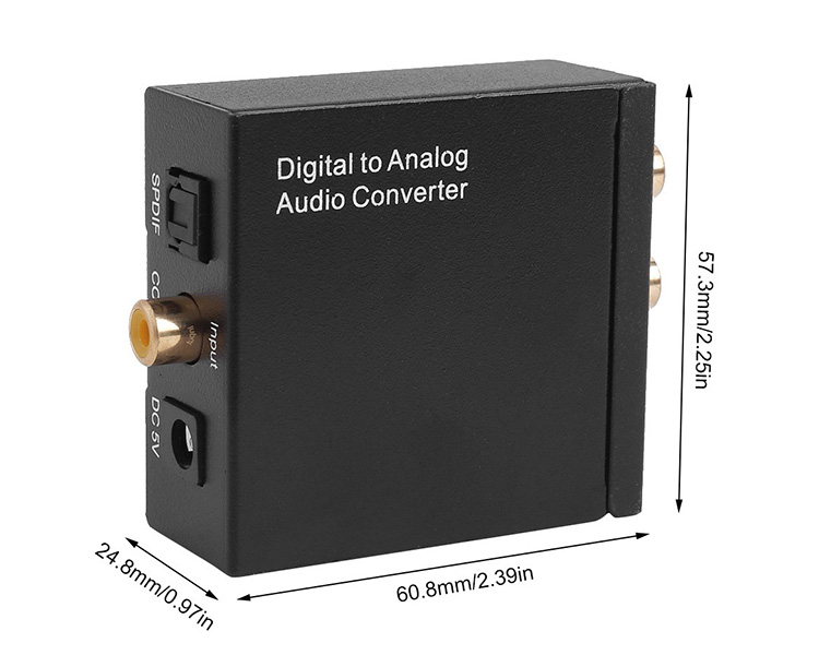
No. 1: DAC Digital to Analog Audio Converter Coaxial Toslink to Analog Stereo L/R RCA 3.5mm Jack Audio Adapter with Optical Cable


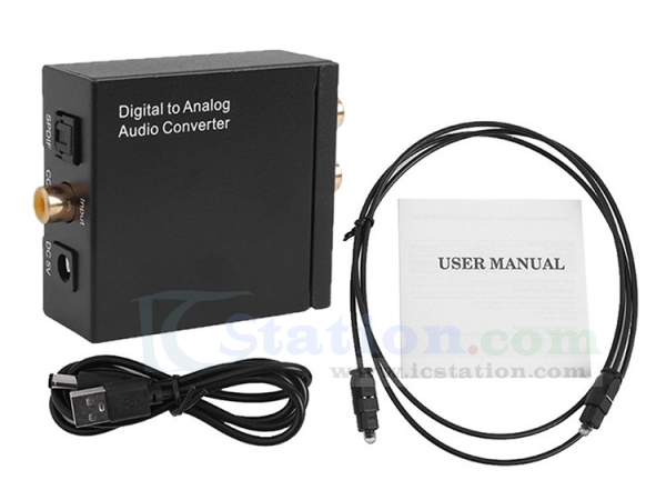
The device successfully decodes perfectly and sends the audio signal without damage and noise into the audio amplifier! Achieve perfect high fidelity lossless audio output function! Perfect audio visual!
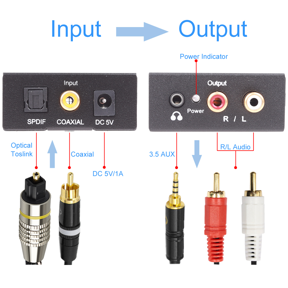
Updated Digital to Analog Audio Converter】: It converts coaxial or toslink digital PCM/LPCM audio signals to analog L/R RCA and 3.5mm Jack Audio (not capable of being reversed). This Digital to Analog Audio Converter is designed for either home or professional audio switching.

It can be used in digital LED TV / cloud TV / Apple TV / blue ray machine / network player / XBOX360 / computer optical fiber coaxial output sound card / digital set top box / network TV box and other electrical equipment with SPDIF coaxial audio / digital optical fiber audio output equipment which can use this converter to convert to analog audio signal L/R channel output.

96KHz Sampling Rate】: Supports sampling rate at 32, 44.1, 48 and 96KHz; 24-bit S/PDIF incoming bit stream on left and right channels. Provides electromagnetic noise-free transmission.  

Easy operation & Wide Application】: With an optical cable and a coaxial cable to transmit digital or analog signals respectively, powered by (5V 1A) USB power cable(Does not come with adapter). Easy to install and simple to operate. 


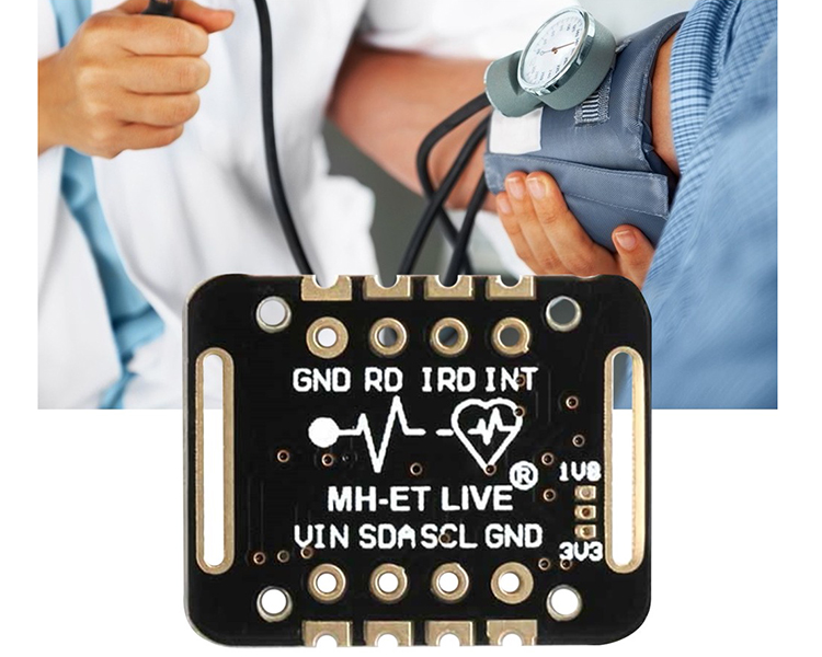
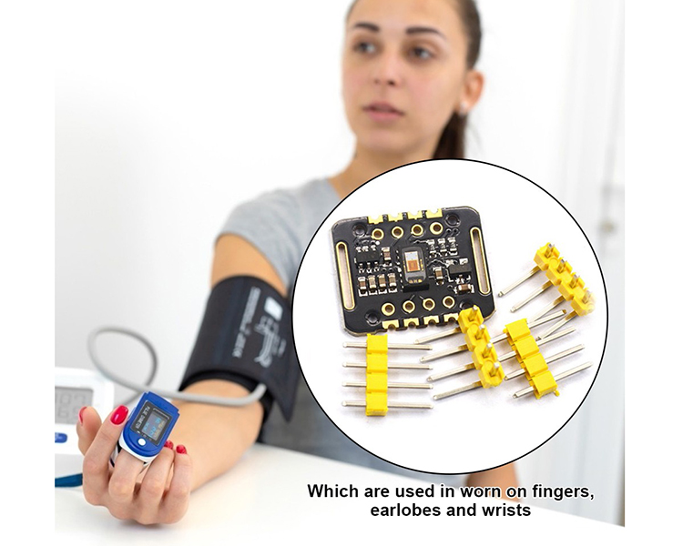
No. 2: MAX30102 1.8V-5V Pulse Oximeter Heart Rate Detection Sensor


MAX30102 blood oxygen concentration sensor. An integrated pulse oximeter and heart rate monitor biosensor module.

It uses an 18V power supply and an independent 50V power supply for internal LEDs, which are used in wearable devices for heart rate and blood oxygen collection and detection.

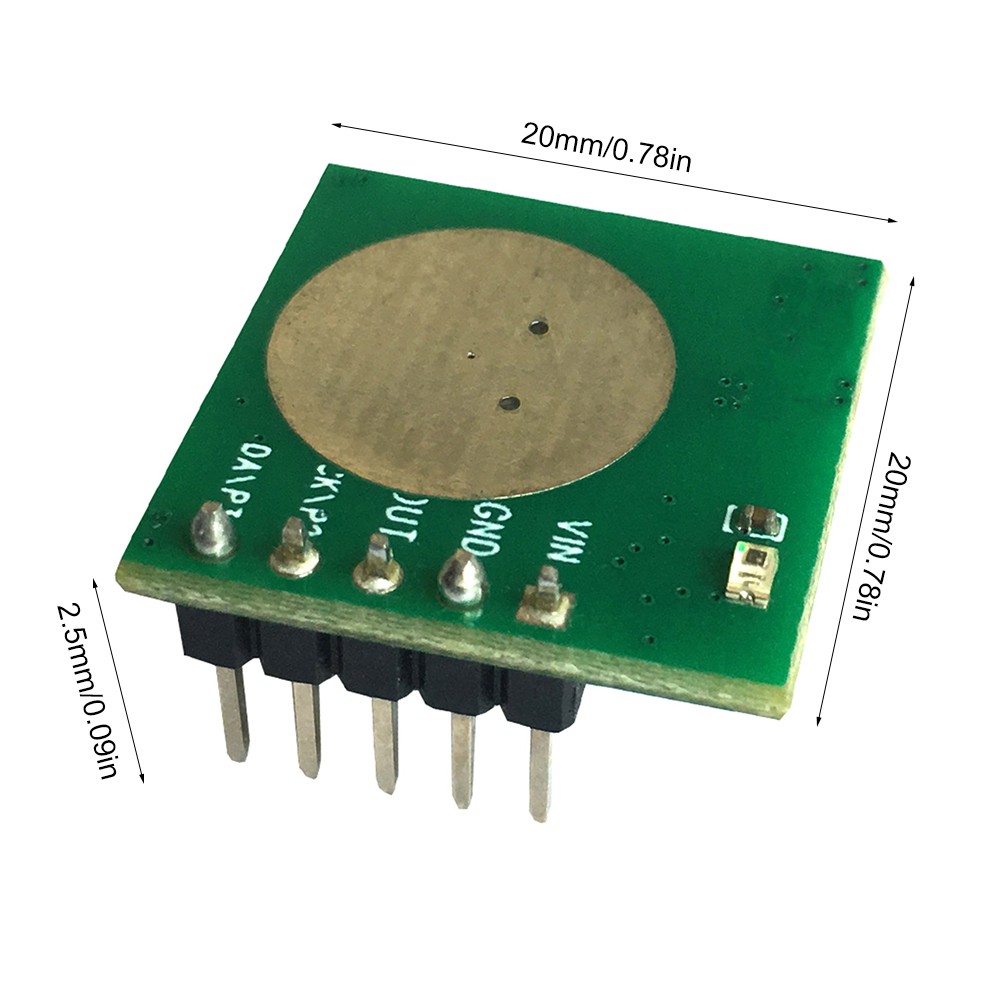
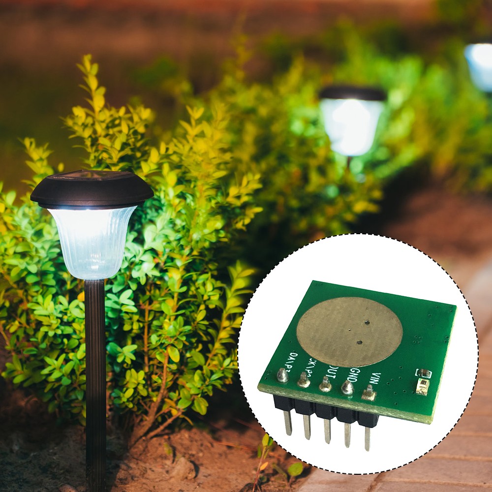
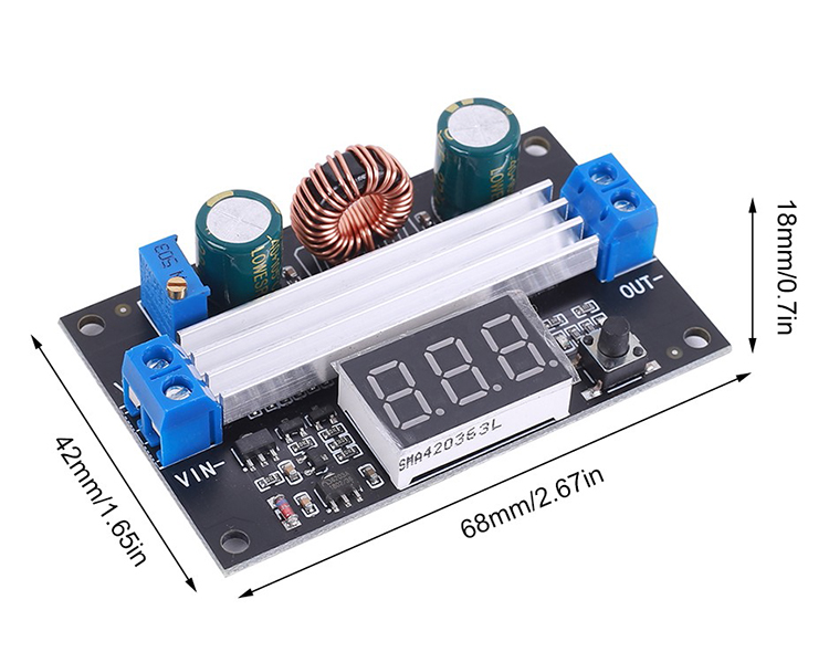
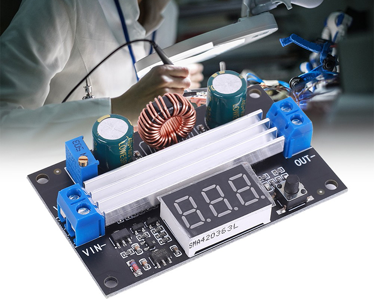
No. 3: 5.8G Microwave Radar Module Infrared Human Body Detector


This is an ultra-low power 5.8G microwave radar module with a working current of only 68uA. 

Combines the high performance of microwave induction and the ultra-high cost-effectiveness of infrared induction. 

Its sensing distance and delay time can be adjusted.
It can perfectly replace infrared pyroelectric induction and make up for the lack of infrared induction. 

Thank you for your attention! For more new products, please check ICStation.com:)

2021年3月10日星期三

Latest Hot Sale New Products!!! FM Radio Wireless Receiver Kits and DC-DC Power Module Recommended!

Dearest Friends,

Much thanks for your support all the way! ICStation has run business for 8 more years now! 2020 is a hard year due to the unexpected COVID-19, many companies closed down, but because of your continues support, we still alive. We still able to provide new products, ship to most of the countries as usual now.

Recently we have some Hot sale new products, especially the FM Radio Kits were very popular and loved by customers. Now Let's look at our latest top 3 new arrivals ! They are might be a nice choice for your new electronics project at the beginning of March! 


It is an 87.0MHz-108.0MHz Wireless FM Radio Receiver DIY Kit. 
With a built-in 4-Bit Red Digital Tube display screen which can display the receiving frequency clearly.


General Features:
1.Automatically search for radio stations
2.Built-in volume adjustment
3.Automatic memory function after power off
4.Support 87Hz-108MHz receiver frequency
5.Built-in 5W power amplifier
6.Power saving mode with backlight off for 5 seconds

Parameter:
1.Product Name:FM Radio Receiver DIY Kit
2.Work Voltage:DC 4.5V~5.5V
3.Output impedance:8ohm
4.Output power:5W
5.Output channel:Mono
6.Receiver Frequency:87.0MHz~108.0MHz
7.Frequency accuracy:0.1MHz
8.Equivalent noise: >=30dB
9.Work Temperature:-40℃~85℃
10.Work Humidity:5%~95%RH
11.Size(Installed):83*69*53mm

Component List:


Schematic Diagram:


Notice:
1.The frequency can be adjusted continuously by keep press button.
2. It is a wireless module. So do not use it in an environment with signal interference.
3.The display can only show for 5 seconds and then enter to power saving mode.

Using Methods:
1.Press left button to decrease receiving frequency.
2.Press right button to decrease receiving frequency.
3.Rotate potentiometer to adjust the volume.

Installation Steps (Please be patient):
Step 1: Install 1pcs 4.7ohm Metal Film Resistor at R7.
Step 2: Install 1pcs 220Kohm Metal Film Resistor at R3.
Step 3: Install 11pcs 10Kohm Metal Film Resistor at R1,R2,R4,R5,R8~R14.
Step 4: Install 1pcs TEA5767 Audio Receiver at TEA5767.Pay attention to the installation direction.
Step 5: Install 1pcs 13.56MHz Crystal Oscillator at Y1.
Step 6: Install 2pcs 22pF Ceramic Capacitor at C1,C2.
Step 7: Install 1pcs DIP-8 IC Socket at LM386.There is a mark on one end of the IC Socket and there is a mark on PCB where the IC Socket can place on.These two marks are corresponding to each other and are used to specify the installation direction of the IC Socket.
Step 8: Install 1pcs DIP-40 IC Socket at U1.There is a mark on one end of the IC Socket and there is a mark on PCB where the IC Socket can place on.These two marks are corresponding to each other and are used to specify the installation direction of the IC Socket.
Step 9: Install 1pcs 50Kohm Potentiometer at R6.
Step 10: Install 3pcs 0.1uF Monolithic Capacitor at C4,C5,C6.
Step 11: Install 4pcs TO-92 S9012 Transistor at Q1~Q4.
Step 12: Install 2pcs 10uF 25V Electrolytic Capacitor at C7,C8.Pay attention to distinguish between positive and negative.The Longer pin is positive pole.
Step 13: Install 1pcs Blue 2*5*7 LED at D13.Pay attention to distinguish between positive and negative.The Longer pin is positive pole.
Step 14: Install 1pcs Red 0.56" 4Bit Common Anode Digital Screen at 056SMG_4.Pay attention to the installation direction.
Step 15: Install 1pcs DC-005 Power Socket at 5V.
Step 16: Install 3pcs 100uF 50V Electrolytic Capacitor at C3,C9,C11. Pay attention to distinguish between positive and negative.The Longer pin is positive pole.
Step 17: Install 1pcs Self-locking Button at S4.
Step 18: Install 2pcs 6*6*20mm Black Button at S1,S2.
Step 19: Install 1pcs DIP-8 IC LM386.There is a mark on one end of the IC and there is a mark on PCB where the IC can place on.These two marks are corresponding to each other and are used to specify the installation direction of the IC.
Step 20: Install 1pcs DIP-40 IC STC89C52.There is a mark on one end of the IC and there is a mark on PCB where the IC can place on.These two marks are corresponding to each other and are used to specify the installation direction of the IC.
Step 21: Install 1pcs Antenna at ANT.Note that the antenna should be installed on the back of the PCB.
Step 22: Connect speaker to PCB at SP by 10cm red/black Cable. The speaker does not distinguish between positive and negative.
Step 23: Tear off the protective film on the surface of the acrylic shell.
Step 24: Fixed speaker on acrylic bottom plate by 4pcs M3*8mm Screw and 4pcs M3 Nut.
Step 25: Install 4pcs M3*8mm Screw and 4pcs M3 Nut on PCB.
Step 26: Install 4pcs M3*10mm Copper Pillar on PCB.
Step 27: Install 4pcs M3*8mm Screw and 4pcs M3 Nut on acrylic front plate.
Step 28: Install PCB module on acrylic front plate.
Step 29: Fix other acrylic plate by 12pcs M3*8mm Screw and 12pcs M3 Nut.
Step 30: Connect to power supply and enjoy the effect.


DIY Kit FM Radio Module Adjustable 76-108MHz Wireless Receiver LCD Display DC 3.7V 5W 8ohm Speaker


Feature:
1.HD display LCD display screen
2.Support storage of 22 radio stations
3.Automatically search for radio stations
4.Built-in 30-level digital volume adjustment
5.Automatic memory function after power off
6.Support 76Hz-108MHz receiver frequency
7.Built-in rechargeable module
8.Built-in 5W power amplifier
9.Power saving mode with backlight off for 20 seconds
10.Support speaker and earphone audio output

Parameter:
1. Work Voltage:DC 3.0V~5.0V
2.Output impedance:8ohm
3.Output power:5W
4.Output channel:Mono for speaker and Dual channel for earphone
5.Frequency:87.0MHz~108.0MHz(Disable Campus Broadcasting Band)
6.Frequency:76.0MHz~108.0MHz(Enable Campus Broadcasting Band)
7.Equivalent noise: >=30dB
8.Work Temperature:-40℃~85℃
9.Work Humidity:5%~95%RH
10.Size(Installed):118*87*27mm

Component List:


Schematic Diagram:


Notice:
1.It cannot receive radio while it is charging.
2.It is a wireless module. So do not use it in an environment with signal interference.
3.Input charging voltage form micro USB on the bigger PCB.

Installation Steps:
Step 1: Install 1pcs 39Kohm Metal Film Resistor at R1.
Step 2: Install 2pcs 10Kohm Metal Film Resistor at R2,R3.
Step 3: Install 1pcs SOP-14 IC LM4863 at U1.There is a mark on one end of the IC and there is a mark on PCB where the IC can place on.These two marks are corresponding to each other and are used to specify the installation direction of the IC Socket.
Step 4: Install 1pcs micro USB socket at J2.
Step 5: Prepare 6pcs pin header.
Step 6: Install 1pcs Charging Module at J7 and fix by 6pcs pin header.
Step 7: Remove black fixed block from 6pcs pin header and fix Charging Module.
Step 8: Install 1pcs 0.1uF Monolithic Capacitor at C2.
Step 9: Install 1pcs 1uF 50V Electrolytic Capacitor at C1.Pay attention to distinguish between positive and negative.The Longer pin is positive pole.
Step 10: Install 1pcs 3.5mm Audio Socket at J5.
Step 11: Cut a pin from 16Pin Female Socket.
Step 12: Install Female Socket at FM.Pay attention to the direction of the cut pin.
Step 13: Install 1pcs Self-locking Button at S6.
Step 14: Install 5pcs 6*6*20mm Black Button at S1-S5.
Step 15: Install 1pcs Self-locking Button Cap on Self-locking Button.
Step 16: Install 1pcs Antenna at ANT.Note that the antenna should be installed on the front of the PCB.
Step 17: Install 1pcs 18650 Battery Box at J1,J3.Pay attention to the positive and negative.Red wire is positive pole.
Step 18: Install 2pcs 15cm black Cable on speaker.
Step 19: Connect speaker to PCB at SP. The speaker does not distinguish between positive and negative.
Step 20: Install 1pcs FM Audio Receiver on Female pins.Pay attention to the direction of the cut pin.
Step 21: Tear off the protective film on the surface of the acrylic shell.
Step 22: Install 4pcs M3*15mm Copper Pillar and 4pcs M3*10mm Screw on Acrylic bottom plate.
Step 23: Fixed speaker on acrylic bottom plate by 4pcs M3*6mm Screw.
Step 24: Install 3pcs M3*6mm Screw and 3pcs M3 Nut on Acrylic bottom plate.Note that the wire should not be placed between the PCB and the acrylic.
Step 25: Fixed main PCB on acrylic bottom plate by 3pcs M3 Nut.Note that the wire should not be placed between the PCB and the acrylic.
Step 26: Adjust the position of the battery box. Do not place the wires under the battery box. The wires can be moved to both ends of the battery box.
Step 27: Fix other acrylic plate by 6pcs M3*6mm Screw and 6pcs M3 Nut.
Step 28: Connect to power supply and enjoy the effect.

Use Method:
1.Keep press AUTO button to automatically search and store the radio stations that can be listened to.
2.Automatically name searchable stations like P01,P02,P02 and so on.
3.Press P+ and P- to switch saved stations.
4.Press V+ and V- to adjust volume from V00 to V30.
5.Switch Campus Broadcasting Band: Keep press V+ and V- before power ON and then turn ON work power switch. It means enable Campus Broadcasting Band if display C1 on LCD. It means disable Campus Broadcasting Band if display C0 on LCD.Available after restart.
6.Enable backlight mode: Keep press P+ and P- before power ON and then turn ON work power switch. It means keep backlight ON if display B1 on LCD. It means the backlight will turn OFF after 20second if display B0 on LCD(This is the power saving mode). Available after restart.
7.It can output audio from speaker and earphone jack. The speaker of the module does not work when the earphone is connected.


DC-DC Boost Power Supply Module DC 3V-35V to DC 3.5V-50V 6A 100W High Power Digital Display

Product Introduction:
It is a booster board, the output voltage is greater than the input voltage. When the output voltage is less than 4V, the onboard voltmeter will not work.

Feature:
1.It has a digital display to display voltage.
2.Its conversion efficiency is high.
3.It has an output voltage potentiometer to adjust the voltage in time.
4.It has a display switch button to switch between input voltage display and output voltage display.

Parameter:
1.Product Name:Boost Module
2.Input Voltage:DC 3.3~35V
3.Input Current:9A(Max)
4.Output Voltage:DC 3.5~50V
5.Output Current:6A(Max)
6.Output Power:100W (input voltage greater than 12V can reach the maximum output of 100W)
7.Conversion Efficiency:96%(Max)
8.Output Ripple:40mV(TYP)
9.Range of Onboard Voltmeter:3~55V
10.Work Temperature:-25℃~85℃
11.Work Humidity:5%~95%RH
12.Size:68*42*18mm

Instructions for Use:
1.The voltmeter can be turned off.Press and hold the switch for 4 seconds,and then it can be turned off by letting go.

2.Input and output voltage measurement error calibration function,long press the switch for more than 4 seconds,after letting go,it will enter the voltage measurement error calibration function.

3.The digital tube flashes to display the voltage calibration ratio value (range -5V~5V).At this time,short press the button to change this value (cycle between -5V~5V).

4.When the voltage value displayed by the voltmeter is too high,lower the reference value (adjust to a negative number).

5.When the voltage value displayed by the voltmeter is low,increase the reference value (adjust to a positive number).

6.After adjusting to the reference value you want,press and hold the button for more than 2 seconds. After letting go,save the set value and return to the normal display voltage.The set correction value will take effect immediately and will not be lost after power failure.


Thanks for your time! We will have more new arrivals soon! 

Electronics Calculator Kit Build

1.Introduction:   ICStation Multi-functional Calculator DIY  Kit is powered by two CR2032 button batteries, integrates five different comput...